
Electric Bike Build
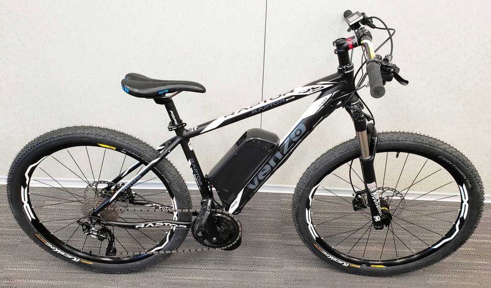
A ground-up electric build on a Venzo Raptor 18-inch aluminum frame, built around a Bafang BBS02 750 W mid-drive at the bottom-bracket shell so torque routes through the bike’s existing chain and gearing. A 52 V down-tube pack drives the integrated controller, with thumb-throttle input and brake-lever motor cutoff. The full assembly was modeled in SolidWorks to verify mount geometry and frame clearance before committing hardware, with the finished build at 20.2 kg.
Objective & Constraints
The objective was to design and integrate a complete electric drivetrain onto an 18-inch aluminum mountain-bike frame, a Venzo Raptor: selecting and packaging a motor and battery, building the high-current power path, and configuring rider controls.
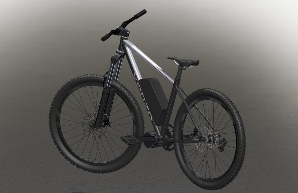
Mass was treated as a primary constraint, so every component was weighed against what it added to the rolling chassis, and the full assembly was modeled in SolidWorks before any hardware was committed. That let motor-mount geometry, battery placement, and clearance against the frame tubes be resolved in CAD rather than discovered on the bench.
Packaging
A Bafang BBS02 mid-drive, rated 750 W at 52 V, was mounted at the bottom-bracket shell. Placing the motor at the bottom bracket routes drive torque through the bike’s existing chain and gearing, so the gear range multiplies motor output just as it does rider input. Compared with a hub motor, it also keeps the drive mass at the frame’s center rather than out at a wheel, concentrating the heaviest single component low and between the wheels.
The lithium-ion pack was carried on the down tube, inside the main triangle, which keeps battery mass low and within the stiffest part of the frame. Both placements were fixed in the SolidWorks model first to confirm the motor and pack cleared the cranks, chainstays, and frame tubes.
Power System
The pack drives the BBS02’s integrated controller through a high-current wiring harness sized for the load. Rider input runs through a thumb throttle, and a brake-lever interlock cuts motor power the instant either brake is applied, so the motor can never drive against the brakes.