
Model Rocket & Compressed Air Launcher
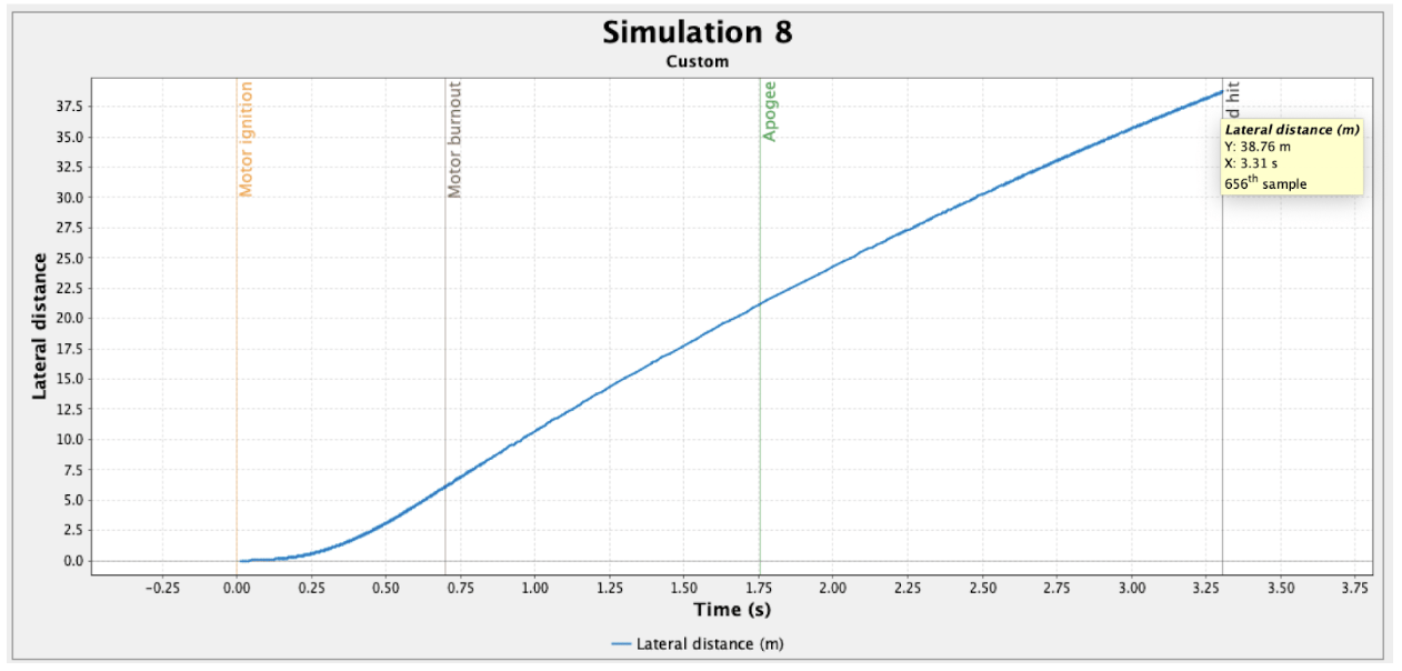
A model rocket engineered for maximum lateral range, flown to a best measured 74 ft 5 in off a compressed-air launcher. The launcher was characterized with a strain gauge in a Wheatstone bridge, certified at 15 PSI input, which resolved an actual delivered pressure of 8.536 PSI rather than the nameplate value. Off-rail velocity from a slow-motion launch, reduced in Tracker, supplied the measured impulse behind an OpenRocket prediction of 38.76 m for the elliptical configuration.
Objective & Constraints
The project applied fundamental aerospace principles to the design and construction of a compressed-air model rocket. The primary objective was maximum lateral range off the rail, held under aerodynamic stability for the whole flight. A second objective was to characterize the launcher itself, so that range predictions could rest on measured thrust rather than the rail’s nameplate pressure.
Fin geometry was the principal design variable, with the conical nose profile carried through unchanged. Iteration started from a fixed baseline airframe and worked out from it:
- 19 cm baseline airframe: a 7 cm conical nose cone, a 5 cm transition, and a 7 cm body tube.
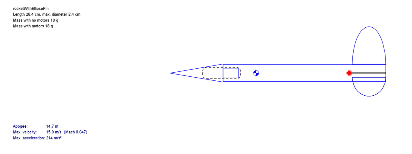
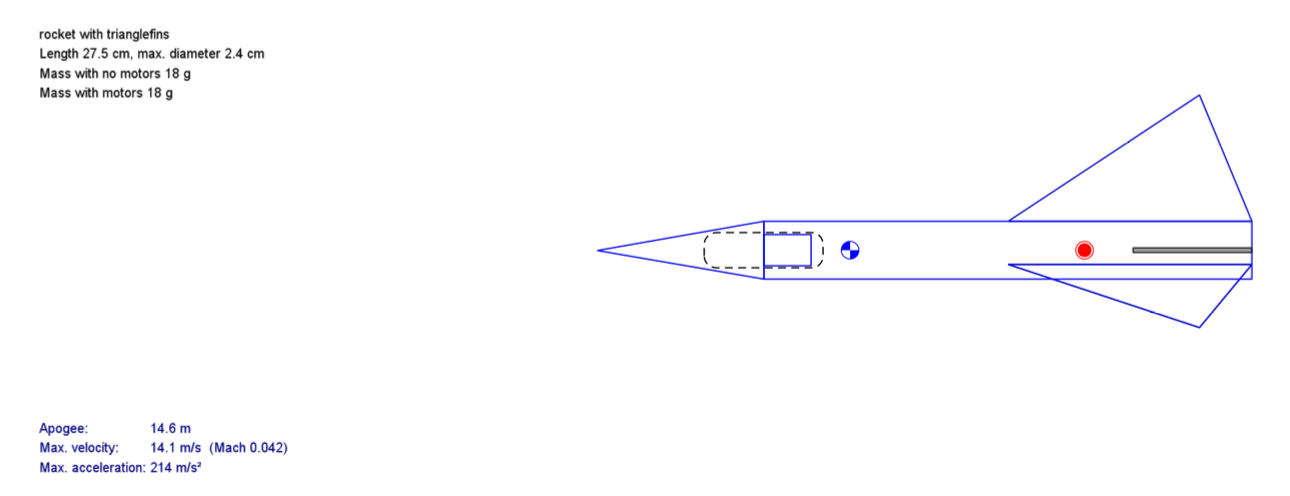
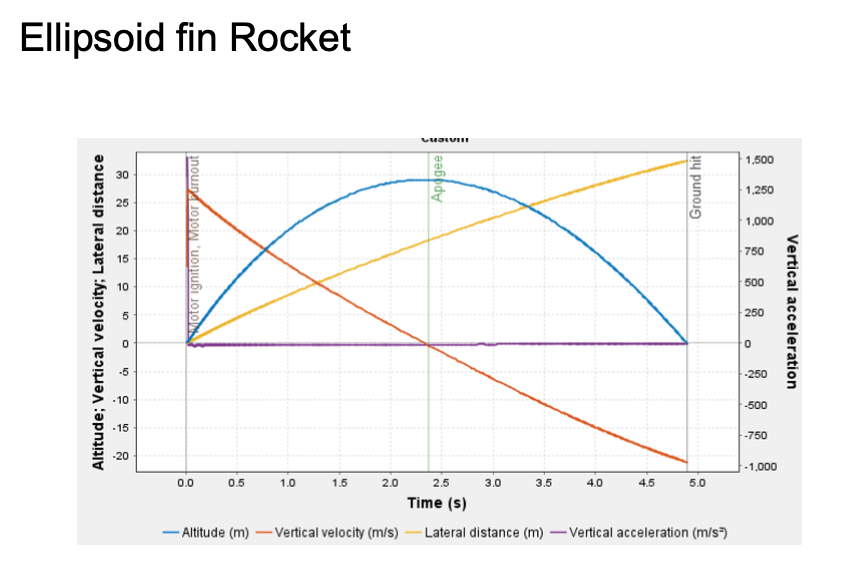
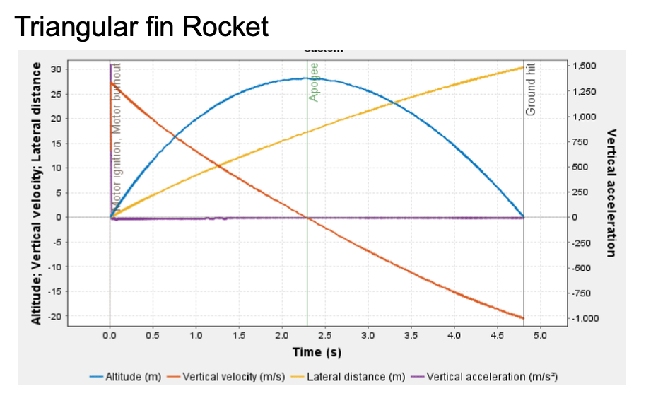
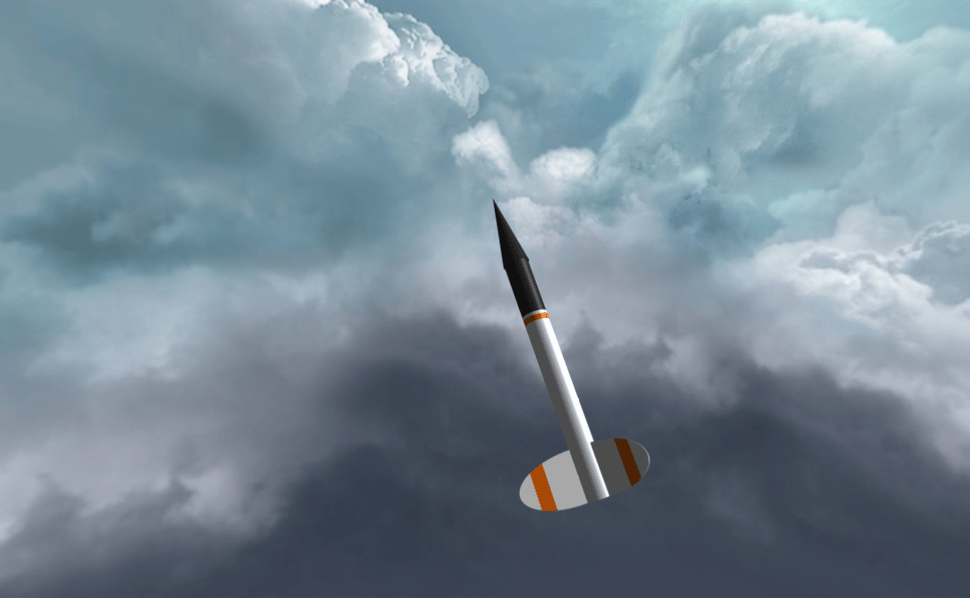
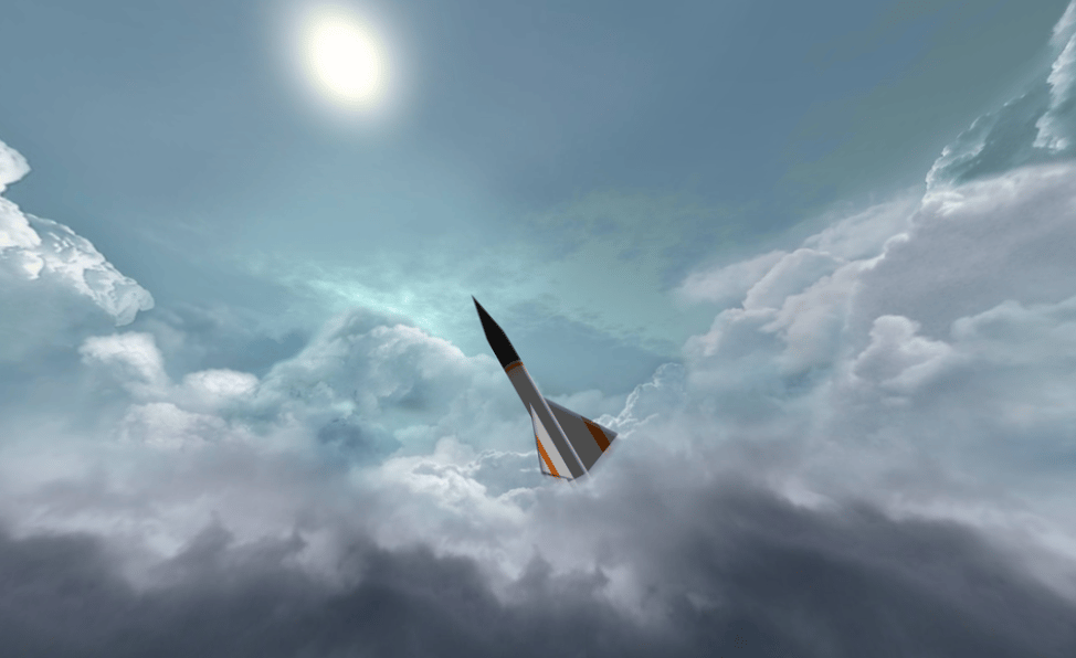
- Body tube, transition, and fins were all varied from that baseline, so the two flown finalists finished longer than it — 28.4 cm and 27.5 cm (Figs. 3 and 4).
- A 20 PSI charge held constant across every launch trial for repeatable conditions.
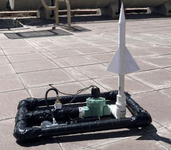
Launcher
Thrust was quantified with a beam-based apparatus rather than assumed. A strain gauge in a Wheatstone bridge sensed the beam’s deflection under load; its output was amplified at a gain of 495 and filtered through an Arduino strain-gauge shield, then sampled against an external mid-supply reference so that both tension and compression registered.
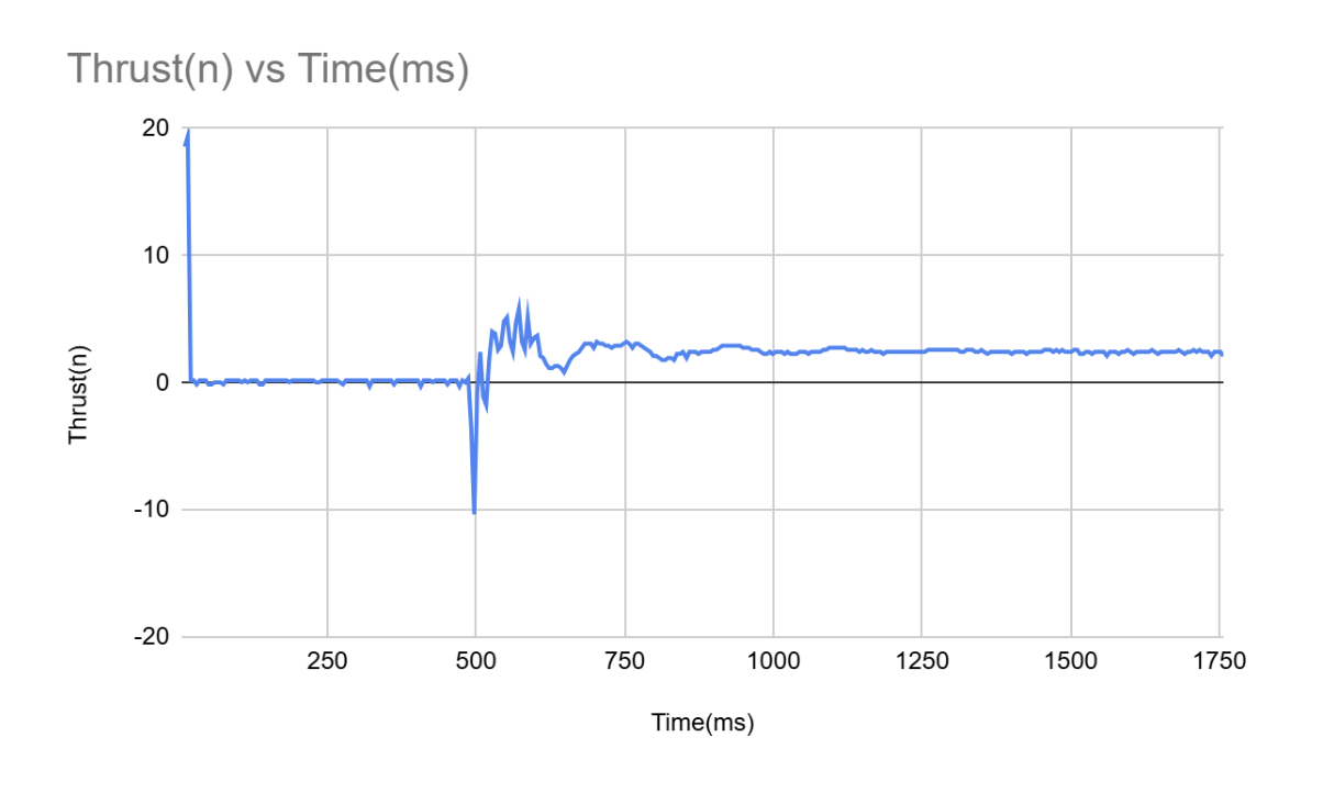
Testing ran at 15 PSI input. The thrust-versus-time trace showed an initial spike as the compressed air released, a brief transient oscillation as the system settled, then a steady force through the main acceleration phase. Reduced through the calibration conversions, the pressure actually delivered to the rocket was 8.536 PSI, well below the charge pressure.
Design & Simulation
Both rockets were designed and iterated in OpenRocket, varying fins, body tube, and transition across many configurations. Two finalists were carried forward: an Elliptical Rocket with rounded elliptical fins that simulated best, and a Freeform Rocket with custom fins shaped to tune the stability margin in calibers and the predicted apogee.
Both shared the sharp conical nose, selected for low drag and simple fabrication, and a reduced body-tube diameter to cut air resistance.
Data Extraction
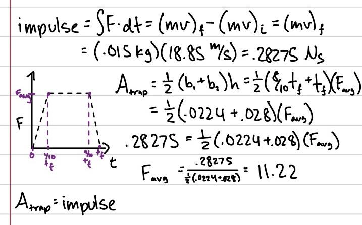
A slow-motion video of an actual launch was tracked in Tracker to recover the rocket’s off-rail velocity. That velocity gave the change in momentum and the impulse, which was fed back into OpenRocket so the prediction rested on measured data.
For the elliptical configuration the simulation returned a predicted lateral distance of 38.76 m.
Results
Two trials were run per design at 20 PSI. The elliptical configuration recorded the greater range and outdistanced the freeform in both trials.
Simulation predicted near-optimal performance; flight testing did not reproduce it. Material limits and experimental uncertainty set the real ceiling, and a range of nose shapes, body lengths, transitions, and fin configurations were evaluated before the two finalists were fixed.
OpenRocket favored small, curved, thin fins. In flight those fins proved structurally insufficient: the rocket spun up and gave back most of its distance. Shorter fuselages worked for the opposite reason, cutting overall mass and buying range. The conical nose was selected for manufacturability — not the most aerodynamically efficient profile, but the one that flew consistently.
| # | Configuration | Range |
|---|---|---|
| 1 | Elliptical Rocket | 74 ft 5 in |
| 2 | Elliptical Rocket | 74 ft 3 in |
| 3 | Freeform Rocket | 58 ft 11 in |
| 4 | Freeform Rocket | 38 ft 1 in |