
Pendulum Clock
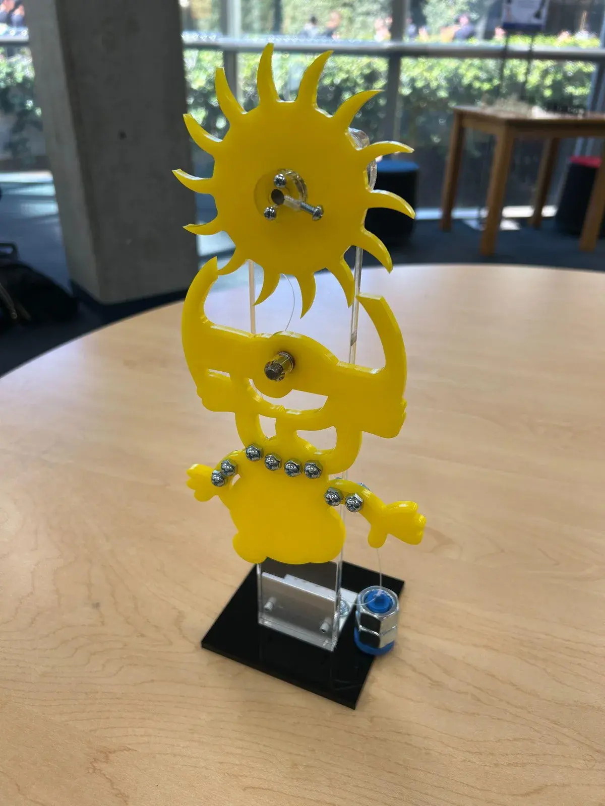
A laser-cut acrylic pendulum clock, used to test how accurately a clock’s timing can be predicted before it is built. Mass properties came from the Fusion 360 model, corrected to the sheet’s measured 0.5 cm thickness, and fed two models of the pendulum. The rigid-body model predicted one revolution of the 14-tooth escapement wheel every 8.38 s, within 3.5% of the measured 8.10 s; the point-mass model predicted 6.66 s, 17.7% short. The gap between them is rotational inertia: spreading the mass across a large plate makes the real pendulum swing more slowly than a point mass would.
Objective & Mechanism
The objective was to predict the timing of a pendulum clock before building it, then measure how close the prediction came.
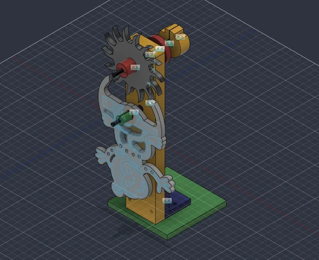
Each full swing of the pendulum lets the escapement wheel advance one of its 14 teeth, while the hanging weight, acting through the escapement, gives the pendulum a small push on every swing to make up for friction. The swing rate therefore sets the speed of the clock: one revolution of the wheel takes 14 pendulum periods, so predicting the timing comes down to predicting the pendulum’s period from its shape and mass.
CAD & Mass Properties
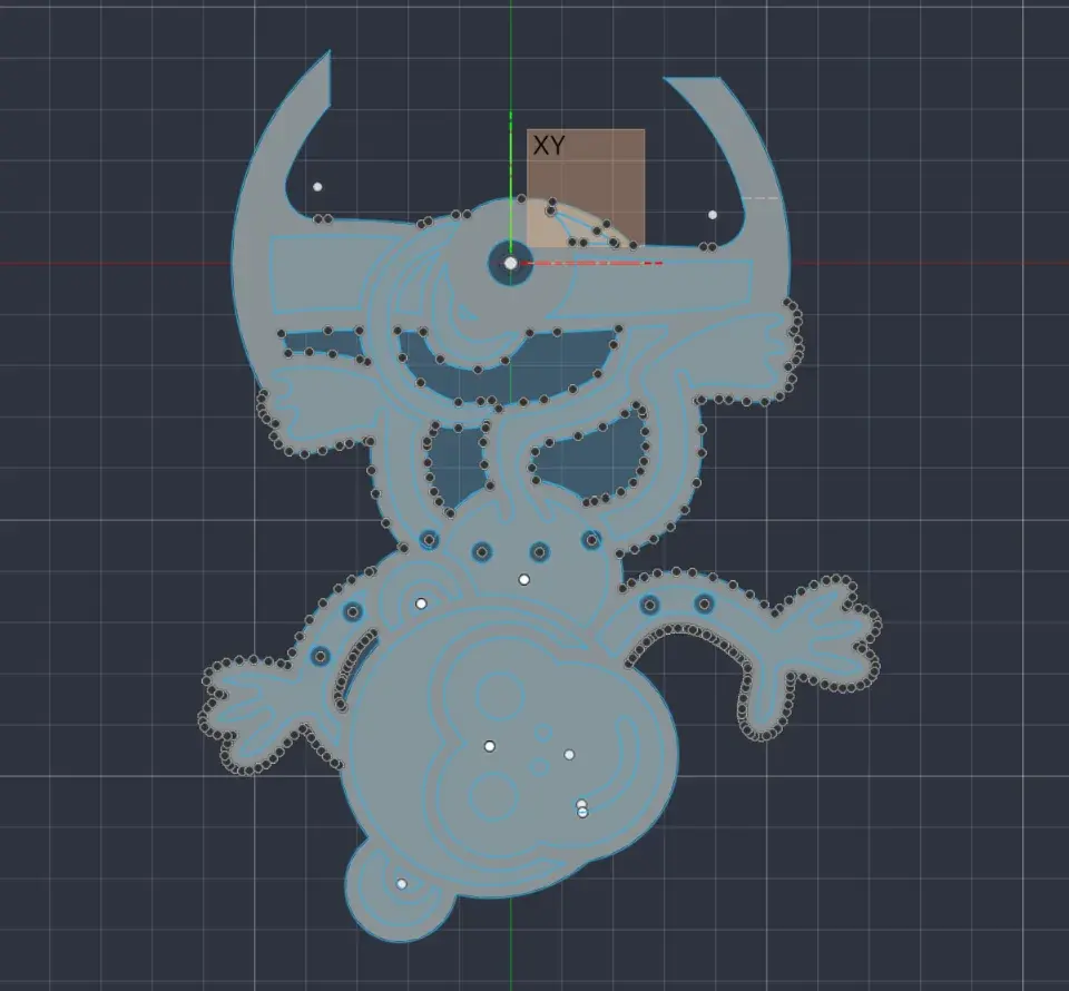
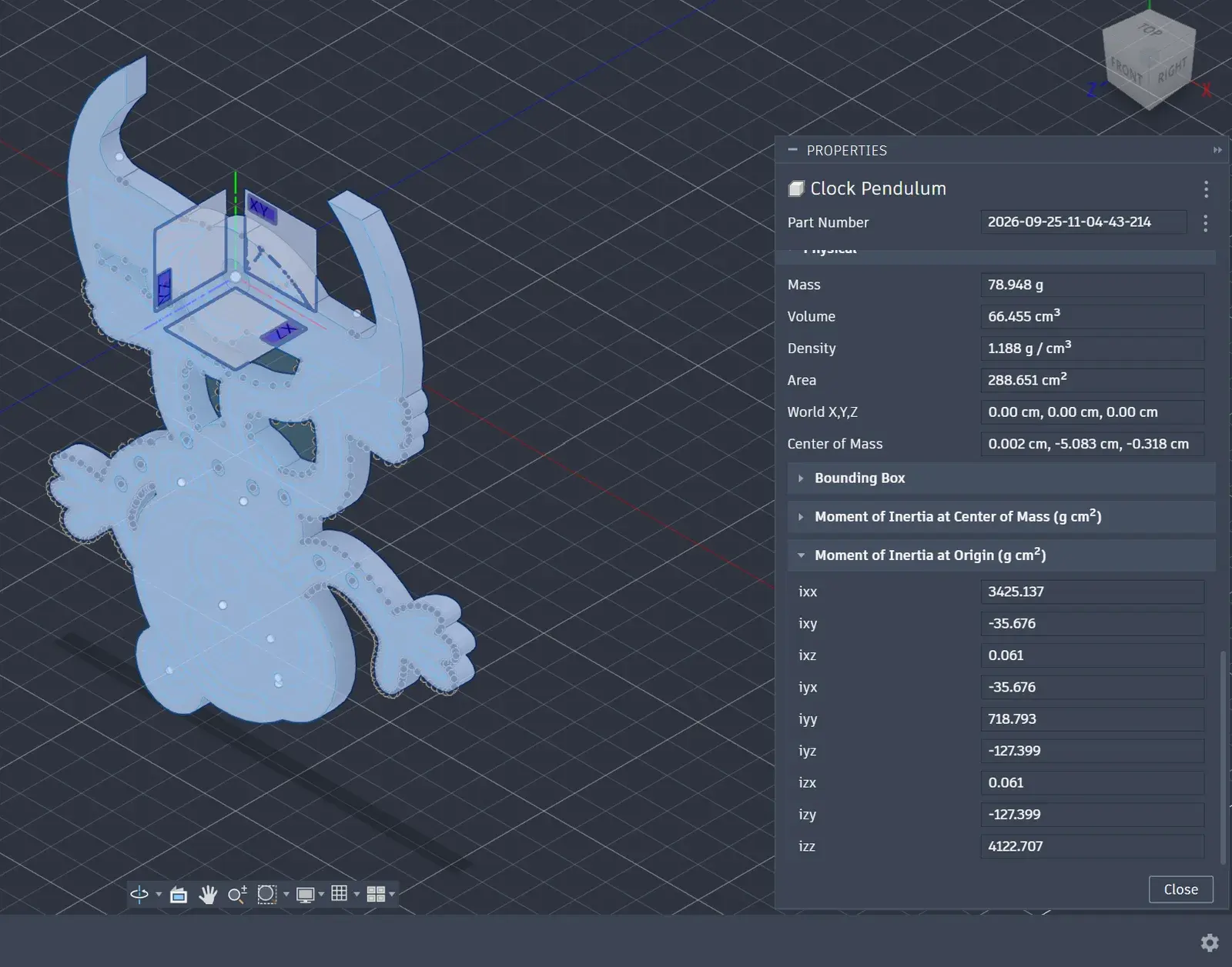
The pendulum was modeled in Fusion 360 with its pivot at the sketch origin. The Measure tool gave the area of the pendulum face, and the Properties window, with the material set to acrylic, gave the distance from the pivot to the acrylic’s center of mass and its moment of inertia about the pivot.
The course template assumed nominal 1/4 in (0.635 cm) acrylic, but the sheet actually used measured 0.5 cm, so every input was carried at the measured thickness. The CAD moment of inertia, drawn at the nominal thickness, was scaled by 0.5 / 0.635, since the inertia of a flat plate of uniform thickness is proportional to that thickness. Eight bolts with two nuts each were added at 4.0 g apiece and treated as point masses at the centers of their holes, with each distance from the pivot taken from driven dimensions in the sketch.
| Input | Name | Value |
|---|---|---|
| Area of pendulum face | A | 104.514 cm² |
| Acrylic thickness, measured | t | 0.5 cm |
| Acrylic density | ρ | 1.188 g/cm³ |
| Pivot to acrylic centroid | La | 5.083 cm |
| Acrylic inertia about the pivot, at 0.5 cm | Ia | 3,246.226 g·cm² |
| Bolt sets, each with two nuts | Nb × Mb | 8 × 4.0 g |
| Escapement wheel teeth | N | 14 |
Timing Models
Two models predicted the period, each serving as a check on the other.
The point-mass model places all of the mass at the center of mass, swinging on a massless rod. The acrylic’s mass follows from its area, thickness, and density (62.08 g), the eight bolt sets bring the total to 94.08 g, and weighting each part by its distance from the pivot puts the center of mass 5.622 cm below it. Then ωn = √(g / Lcom) = 13.20 rad/s, a period of 0.4759 s, and 6.66 s per revolution of the escapement wheel.
The rigid-body model treats the pendulum as a solid body rotating about the pivot, using its moment of inertia instead of a single point. The acrylic contributes 3,246.2 g·cm² and the bolts, as point masses at Mb·L², another 1,460.8 g·cm², for 4,707.0 g·cm² in total. Then ωn = √(Mt·g·Lcom / Itotal) = 10.49 rad/s, a period of 0.5988 s, and 8.38 s per revolution.
Both models assume negligible pivot friction and air resistance, small swing angles (sin θ ≈ θ), a laser-cut part that matches the CAD, and an escapement that does not change the pendulum’s natural frequency. The small bronze bearing pressed into the pivot hole was left out, since its mass sits at the pivot. Every value was computed in a spreadsheet with named cells, so each equation reads in terms of its variables.
Testing
Three measurements checked the predictions. The acrylic pendulum alone weighed 62 g on a digital scale. With the eight bolts installed, it was balanced on a finger to locate its center of mass, 55.5 mm from the pivot.
For the timing, the clock was wound and the weight released so the escapement teeth caught the pallets on the pendulum. Once it was ticking steadily, one full revolution of the escapement wheel was timed at 8.10 s. Dividing by the 14 teeth gives a measured period of 0.5786 s and a natural frequency of 1.728 Hz (10.86 rad/s).
Results
The predicted acrylic mass matched the scale to within 0.13%, and the calculated center of mass sat 1.29% farther from the pivot than the balance point, a 0.7 mm difference inside the 1 to 2 mm resolution of balancing on a finger.
The rigid-body model was about five times more accurate. The difference is rotational inertia: the point-mass model effectively uses Mt·Lcom² = 2,973 g·cm², while the rigid-body analysis found 4,707 g·cm², 58% more. Mass spread out around the center of mass adds rotational inertia without adding any gravity torque, so the real pendulum swings more slowly than a point mass would. A point-mass model suits a small, heavy bob on a light rod; this pendulum spreads its mass across a large acrylic plate.
Measuring the sheet mattered most for mass. At the nominal 0.635 cm thickness, the calculated acrylic mass was 78.84 g, 27.2% above the scale reading, yet the timing errors moved only slightly, to 4.6% and 18.3%, because thickness scales the acrylic’s weight and its inertia by the same ratio.
Even with the rigid-body model, the real clock ran 0.28 s per revolution faster than predicted. The likeliest cause is the escapement itself: near the end of each swing, the wheel pushes the pallets back toward center, acting as extra restoring torque that shortens the period, which neither model includes. Timing a single revolution by hand adds error as well, which averaging several consecutive revolutions would reduce. The point-mass model stays useful as a quick hand check that catches gross mistakes such as a unit conversion error, but the rigid-body model is the one to design a pendulum to.
| Quantity | Point mass | Rigid body | Measured |
|---|---|---|---|
| Natural frequency | 2.101 Hz | 1.670 Hz | 1.728 Hz |
| Period | 0.4759 s | 0.5988 s | 0.5786 s |
| Time per wheel revolution | 6.66 s | 8.38 s | 8.10 s |
| Error in timing | 17.7% | 3.5% | – |