
Self-Balancing Autonomous Robot
A two-wheeled self-balancing robot that autonomously solves a 10 m maze in 13.62 seconds, the fastest recorded run. A Kalman filter fuses gyroscope and accelerometer data into a stable tilt estimate, which a cascaded PID loop corrects at 200 Hz. The full sensing, control, and navigation stack runs on a single Arduino Nano, with motor torque delivered through a TB6612FNG driver and no blocking calls anywhere in the control path.
Estimation & Sensor Fusion
Tilt is measured by an MPU6050 IMU, which provides both linear acceleration and angular rate.
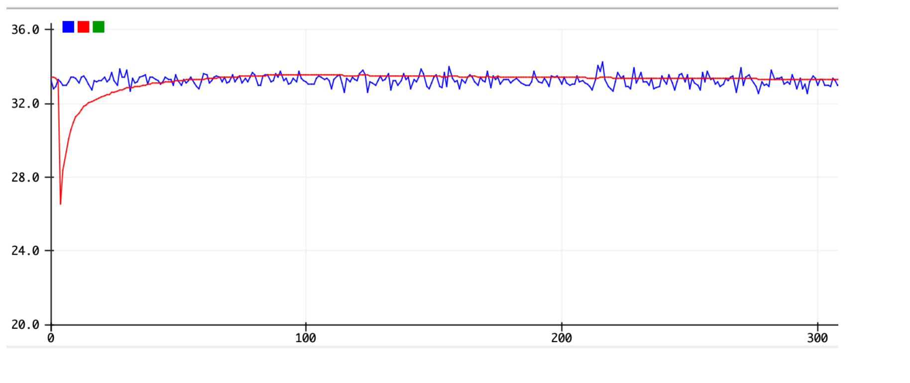
Neither sensor is reliable on its own. The gyroscope drifts as its readings are integrated, and the accelerometer is noisy and easily corrupted by the chassis’s own motion.
A Kalman filter fuses the two into a single stable tilt estimate. It trusts the gyroscope over short intervals and uses the accelerometer to correct long-term drift, which is what makes a clean angle possible on a platform that is always accelerating.
// One-dimensional Kalman filter: fuses the gyro rate with the
// accelerometer angle into a single drift-free tilt estimate.
float kalmanUpdate(float accelAngle, float gyroRate, float dt) {
  // Predict: integrate the gyro, grow the error covariance
  angle += (gyroRate - bias) * dt;
  P[0][0] += dt * (dt*P[1][1] - P[0][1] - P[1][0] + Q_angle);
  P[0][1] -= dt * P[1][1];
  P[1][0] -= dt * P[1][1];
  P[1][1] += Q_bias * dt;

  // Update: correct long-term drift with the accelerometer
  float S  = P[0][0] + R_measure;       // innovation covariance
  float K0 = P[0][0] / S, K1 = P[1][0] / S;
  float y  = accelAngle - angle;        // innovation
  angle += K0 * y;
  bias  += K1 * y;

  float p00 = P[0][0], p01 = P[0][1];
  P[0][0] -= K0 * p00;  P[0][1] -= K0 * p01;
  P[1][0] -= K1 * p00;  P[1][1] -= K1 * p01;
  return angle;
}Control Architecture
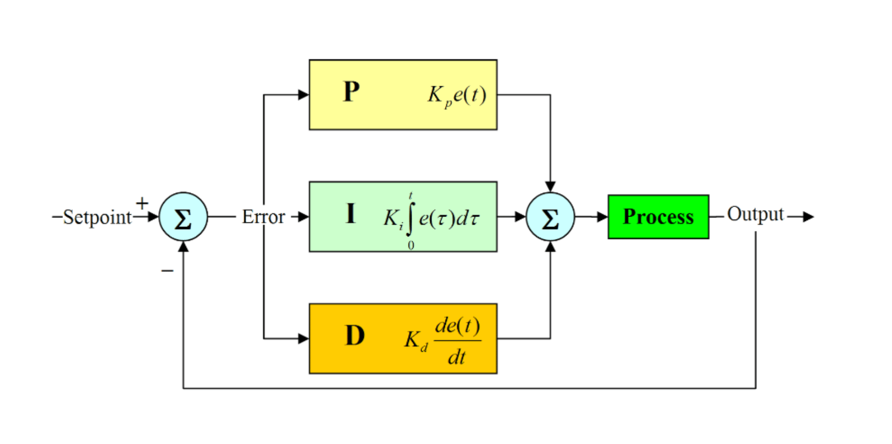
A PID loop holds the balance setpoint and commands motor torque through a TB6612FNG dual H-bridge.
Wheel speed is recovered from quadrature encoders (26 counts per revolution, 30:1 gearing) and low-pass filtered at 20 Hz to strip quantization noise before it reaches the loop.
Motion comes from three superimposed controllers, each correcting a different part of the robot’s behavior:
- Balance loop: keeps the body vertical.
- Speed loop: drives forward and back by biasing the tilt setpoint, so the balance loop chases the lean.
- Steering loop: turns the robot by commanding a differential between the two wheels.
// ---- Balance loop (PD): 5 ms / 200 Hz ----
int balancePD(float angle, float gyroRate) {
  return Kp_bal * (angle - angleSetpoint) + Kd_bal * gyroRate;
}

// ---- Speed loop (PI), 40 ms, biases the tilt setpoint ----
int speedPI(int targetSpeed, int wheelSpeed) {
  int err   = targetSpeed - wheelSpeed;
  speedInt += err;
  speedInt  = constrain(speedInt, -SPEED_I_MAX, SPEED_I_MAX);
  return Kp_spd * err + Ki_spd * speedInt;
}

// ---- Steering loop (PD), 40 ms, wheel differential ----
int turnPD(int targetYaw, float yawRate) {
  return Kp_turn * (targetYaw - yawRate) + Kd_turn * yawRate;
}

// Superimpose the three loops, then split to the two motors
int bal  = balancePD(angle, gyroRate);
int spd  = speedPI(targetSpeed, wheelSpeed);
int turn = turnPD(targetYaw, yawRate);
setMotors(bal + spd - turn,    // left  (PWMA)
bal + spd + turn); // right (PWMB)Firmware
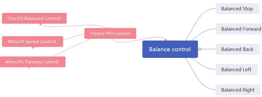
The firmware is written in C++ as a set of nested loops running at different fixed rates. A hardware timer interrupt drives the fixed-rate control tick, and encoder edges are counted on their own interrupts.
- 5 ms (about 200 Hz): the inner balance loop.
- 40 ms (about 25 Hz): the outer speed and steering loops.
Nothing in the control path blocks. There are no delay() calls, so sensing and driving never stall the balance loop, and the robot cannot fall while the processor is busy elsewhere.
// ---- Pin map (Arduino Nano) ----
#define ENC_L   2     // M2A  left encoder pulse
#define ENC_R   4     // M1A  right encoder pulse
#define PWM_L   5     // PWMA left motor PWM
#define PWM_R   6     // PWMB right motor PWM
#define AIN1    7     // right motor direction
#define BIN1    12    // left  motor direction
#define STBY    8     // TB6612FNG enable
#define TRIG    11    // HC-SR04 trigger
#define ECHO    A3    // HC-SR04 echo
// MPU6050 on I2C: SDA A4, SCL A5

// Fixed-rate control tick, driven by a hardware timer, never delay()
ISR(TIMER2_OVF_vect) {
  static uint8_t div = 0;
  readIMU();                                   // every 5 ms
  angle = kalmanUpdate(accelAngle, gyroRate, 0.005f);
  int cmd = balancePD(angle, gyroRate);        // 200 Hz inner loop

  if (++div >= 8) {                            // every 40 ms ≈ 25 Hz
    div = 0;
    cmd += speedPI(targetSpeed, wheelSpeed);
    cmd -= turnPD(targetYaw, yawRate);
  }
  driveMotors(cmd);
}

// Encoder edges counted on their own pin-change interrupts
void encoderLeftISR()  { leftCount++;  }
void encoderRightISR() { rightCount++; }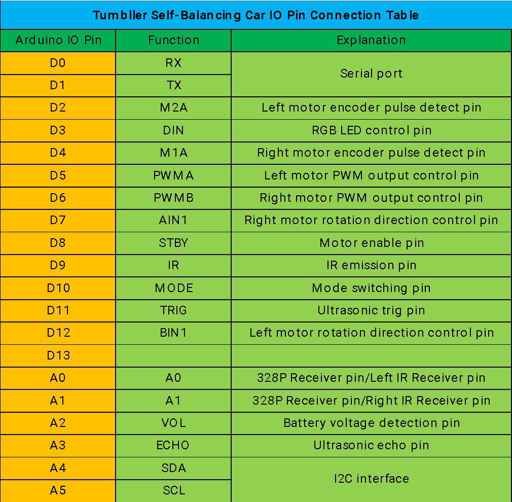
Navigation
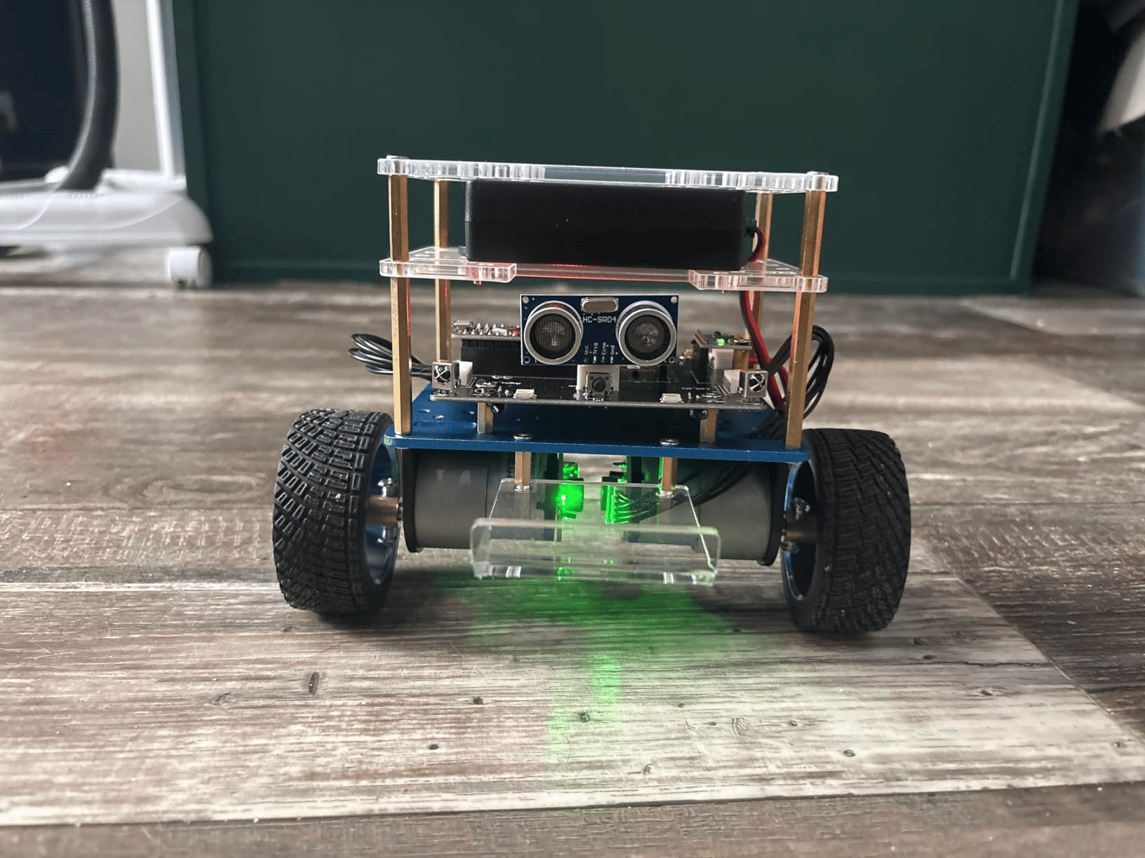
A single forward-facing HC-SR04 ultrasonic rangefinder measures the distance to the wall ahead.
The robot drives forward while the path is clear, then triggers a turn once that distance drops below a threshold and re-samples until a clear corridor opens.
Each turn injects a differential-torque disturbance into the chassis, which the balance loop rejects while still steering. Sequencing these wall detections carries the robot through the entire course autonomously.
A second control mode moves perception off-board. A companion Python program runs convolution-based edge detection on a laptop camera feed, identifies objects in the path, and sends drive commands over Bluetooth. Balancing stays local on the Nano while higher-level navigation is supervised from the host.
// Forward HC-SR04: threshold-triggered turns in the outer loop
long readDistanceCM() {
  digitalWrite(TRIG, LOW);  delayMicroseconds(2);
  digitalWrite(TRIG, HIGH); delayMicroseconds(10);
  digitalWrite(TRIG, LOW);
  long us = pulseIn(ECHO, HIGH, 25000);   // ~4 m timeout
  return us * 0.0343 / 2;                 // speed of sound
}

void navigate() {
  long d = readDistanceCM();
  if (d > WALL_THRESHOLD || d == 0) {
    targetSpeed = CRUISE;     // corridor clear, drive on
    targetYaw   = 0;
  } else {
    targetSpeed = 0;          // wall ahead, pivot, re-sample
    targetYaw   = TURN_RATE;
  }
}Results
- Course: 10 m autonomous maze.
- Time: 13.62 seconds, the fastest recorded run.
- Stability: held its balance under disturbance and at full forward speed, from start to finish.
The same platform was later fitted with a gripper end-effector. The balance loop handles the added mass and shifted center of gravity, showing the controller has the margin to tolerate meaningful changes in the platform’s dynamics.