
Formula SAE Chassis & Powertrain Design
Design and analysis work for Triton Racing, UC San Diego’s Formula SAE team, across the chassis and powertrain groups, carried out against the team’s frame and powertrain CAD, its drawing standards, and the 2027 Formula SAE rules.
A steering rack mount, an electric motor selection and motor mount, and three supporting parts, each taken from a stated load case through design and SolidWorks FEA. The rack mount fills a 4.45 mm gap beneath the steering rack with a tapped 4130 block that carries a 7,000 N steering load at a factor of safety of 3.7 on welded steel, adding about 0.01° of steering play. A weighted decision matrix selected the Emrax 208 for the acceleration event, and its stator-side mount was cut 24% in mass through FEA iteration. The supporting work covers an engine mount tab at a factor of safety of about 91, a 16.8 lb wheel stand weldment sized for 330 lb, and a three-sheet anti-roll bar drawing package with a bill of materials.
Rack Mount Constraints
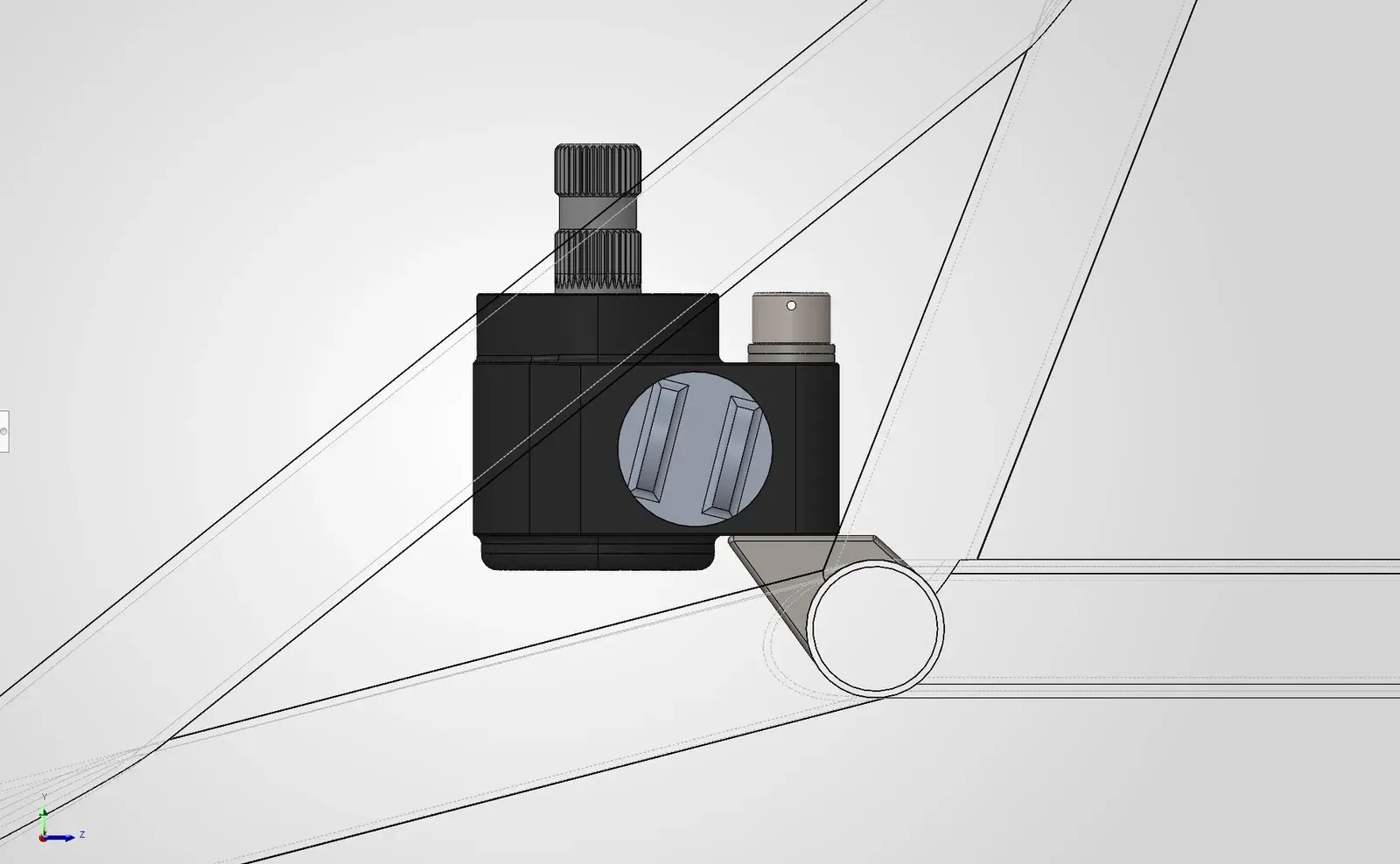
The steering rack had to be fixed to the frame without moving it, since its height sets the tie rod angles. That left a 4.45 mm gap between the rack’s mounting ears and the front cross tube, no room for a nut beneath the ears, and about 10 mm of thread depth before the tube. The rack bar and tie rods slide about 30 mm each way, so only the housing could be held, and the pinion housing below the ears forced the mount to stop 28 mm behind the tube center.
The rulebook set the rest. Steering bolts are critical fasteners (T.8.2) and need positive locking, which lock washers and thread locker do not provide (T.8.3). Steering free play must stay under 7° (V.3.2.5), so the mount had to be stiff, and the cockpit template passes directly over the rack (T.1.2), so nothing could stand above the housing. Both bolts also had to come out from the top, so the rack can be removed without reaching under the car, against a 200 g target for the mount and its hardware.
Rack Mount Concept
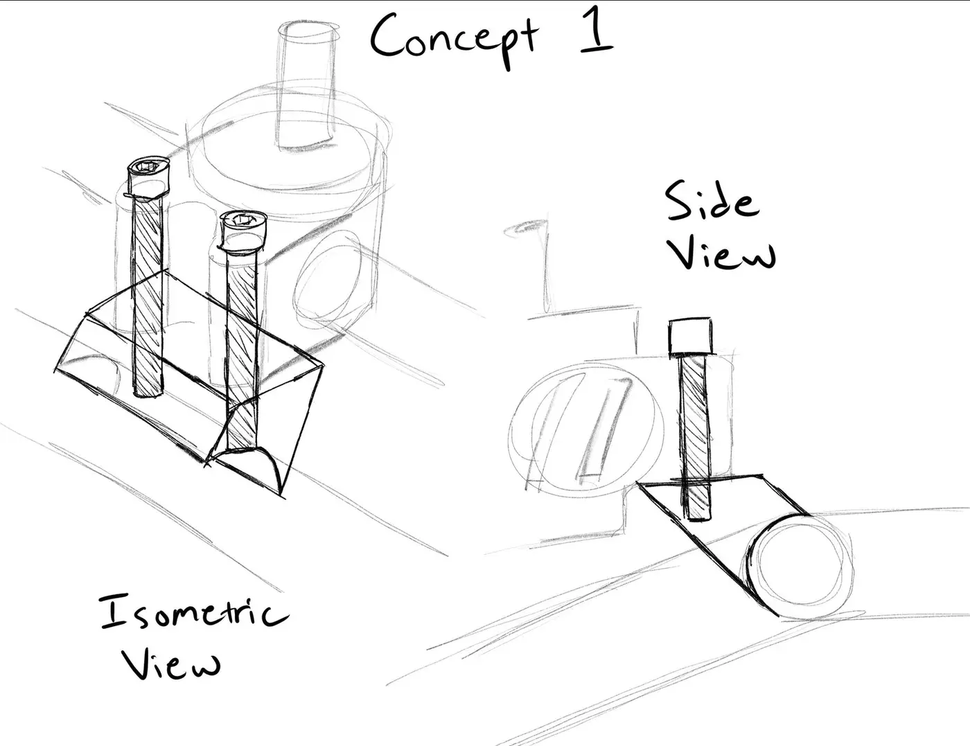
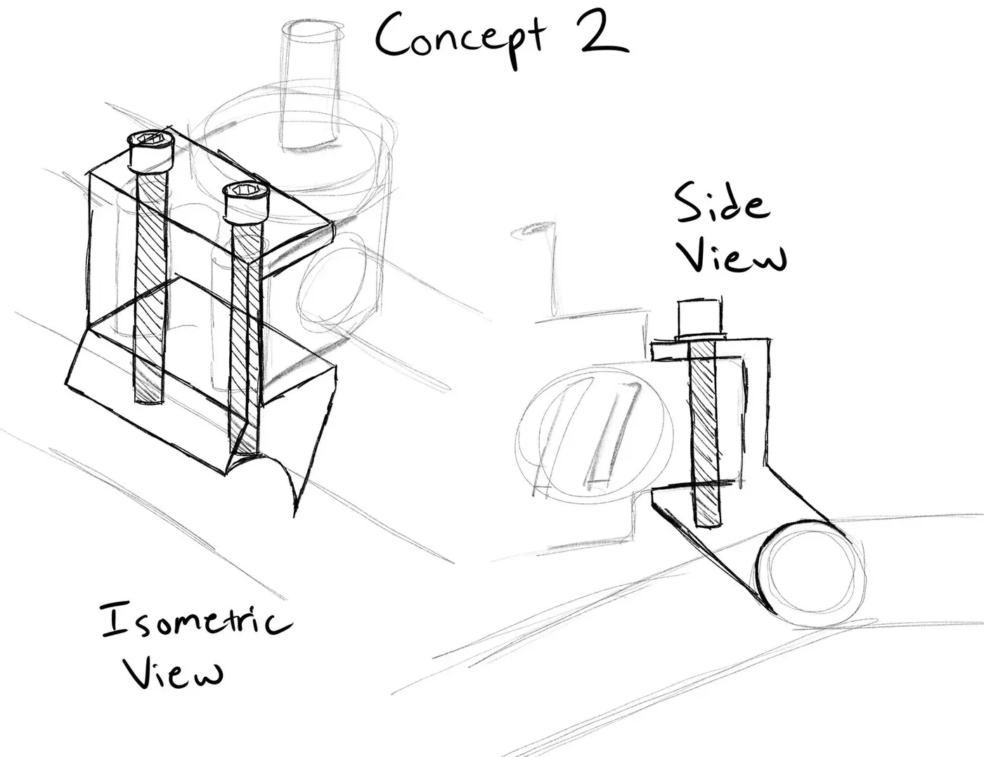
Two concepts were sketched and compared. The first is a wedge block welded to the cross tube that fills the gap and carries the threads, so no nut is needed under the ears. The second adds a cap above the ears to sandwich them. The cap was dropped because the washers already clamp the ears, so it only added a second part, mass, and height close to the cockpit template. A bent sheet bracket was ruled out as well, since it offered only about 5 mm of thread and would flex.
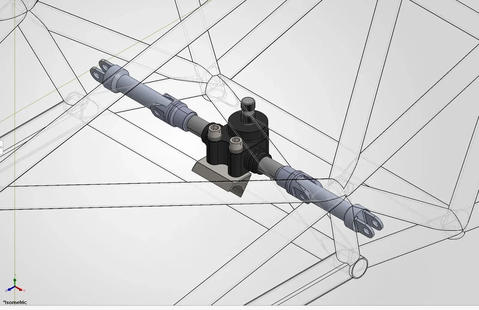
The block is 4130 chromoly, the same steel as the frame, so it welds on with the same filler and behaves as part of the structure. Steel threads survive repeated rack removal far better than aluminum, and steel’s roughly threefold stiffness keeps the steering tight; at about 117 g, its density barely matters. Two McMaster 90117A630 3/8"-16 alloy steel socket head screws, drilled for safety wire, pass down through the rack ears into the block, each over two MIL-spec washers that set about 9.3 mm of thread engagement, roughly one bolt diameter. With its hardware, the mount weighs about 181 g, inside the 200 g target.
Rack Mount Load Case & FEA
The rulebook sets no test load for the steering rack, so the design case was 100 Nm at the steering wheel, the minimum a Formula SAE design judge recommends because a startled driver can pull far harder than normal. Assuming 90 mm of rack travel per turn of the wheel gives a pinion radius of about 14.3 mm, so the rack sees F = T / r ≈ 7,000 N along its axis, passing from the housing into the two bolts, through the block, and into the cross tube.
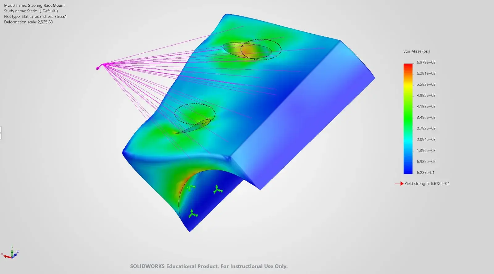
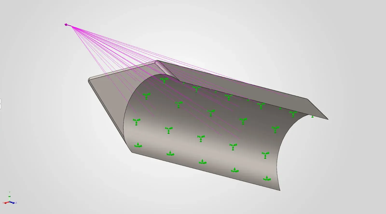
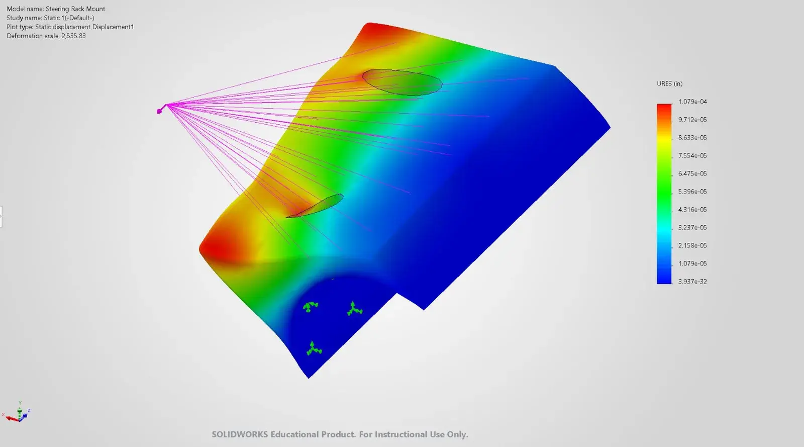
In SolidWorks Simulation, the curved underside was fixed where it is welded to the tube. The 7,000 N was applied as a remote load at the rack centerline, 33 mm up and 33 mm back from the tube and tied to both tapped holes, so the block is twisted as well as sheared. The mesh used standard 3 mm elements, about 4,900 in all.
- Peak von Mises stress: 6,979 psi (48 MPa), at the bolt holes and the edge where the block meets the tube.
- Factor of safety: 3.7 against the 180 MPa the rules assign to welded steel (F.3.4.2.b), and 9.6 against the 460 MPa base yield.
- Deflection: 0.003 mm. At about 0.25 mm of rack travel per degree of steering, that adds roughly 0.01° of play against the 7° limit.
Bumps and curb strikes feed back through the tie rods along the same load path, and the block would need about 3.7 times the design load to yield. The next iteration reruns the study with the real pinion size from the steering lead and with the frame tube modeled rather than fixed, then trims material from the back of the block where the margin allows.
Motor Selection
Five Emrax motors were compared for the acceleration event, on a 400 V, 220 A pack in a 240 kg car. The rules narrowed the field before any scoring. EV.3.3.1 caps measured power at 80 kW, below the 88 kW the pack could supply, so a motor making far more than 80 kW is only extra mass. EV.3.3.2 caps voltage at 600 V, and the 188’s medium-voltage version tops out at 390 V. Every Emrax is an outrunner with cooling vents, so each needs a scatter shield (T.5.3) that the mount must leave room for.
A weighted decision matrix scored each motor from 1 to 5. Usable power under the cap and mass carried the most weight, since the car is light and power above 80 kW cannot be used. Peak torque came next, because gearing can recover it, followed by packaging inside the frame and ahead of the rear bulkhead, compatibility with the 400 V pack, and continuous power, which barely matters for a single acceleration run.
The Emrax 208 scored 88 against the 228’s 86. It is the lightest motor that can still use the full 80 kW, and its torque deficit to the 228 (150 Nm against 220 Nm) can be recovered with a rear sprocket giving about 1.5 times the reduction. It is also smaller to package and puts less chain force into the mount. For endurance, where continuous power and efficiency dominate, the 228 and its 75 kW continuous rating would be the stronger choice.
| Criterion | Weight | 188 | 208 | 228 | 268 | 348 |
|---|---|---|---|---|---|---|
| Usable power (80 kW cap) | 5 | 2 | 5 | 5 | 5 | 5 |
| Mass | 5 | 5 | 4 | 3 | 2 | 1 |
| Peak torque | 4 | 2 | 4 | 5 | 5 | 5 |
| Size (fits in frame) | 3 | 5 | 5 | 4 | 2 | 1 |
| Works on 400 V | 2 | 2 | 5 | 5 | 5 | 5 |
| Continuous power | 1 | 1 | 2 | 4 | 5 | 5 |
| Weighted total | 63 | 88 | 86 | 76 | 68 |
Motor Mount
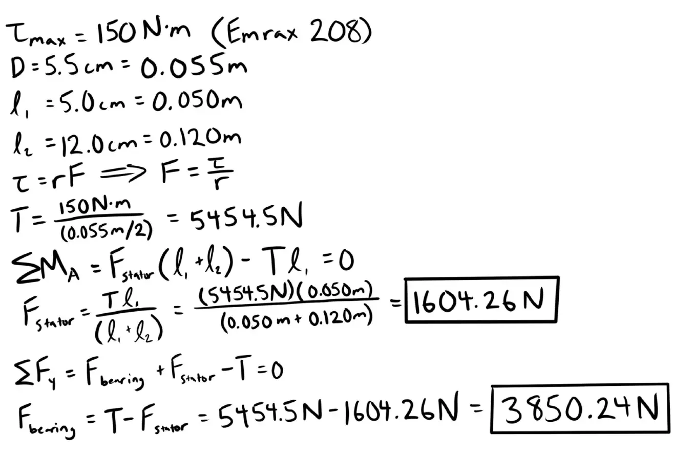
The selected motor’s 150 Nm peak torque sets the mount loads. On a 5.5 cm pitch-diameter drive sprocket, the chain tension is 5,454.5 N, and summing moments about the bearing-side support puts 1,604 N into the stator-side mount and 3,850 N into the bearing side.
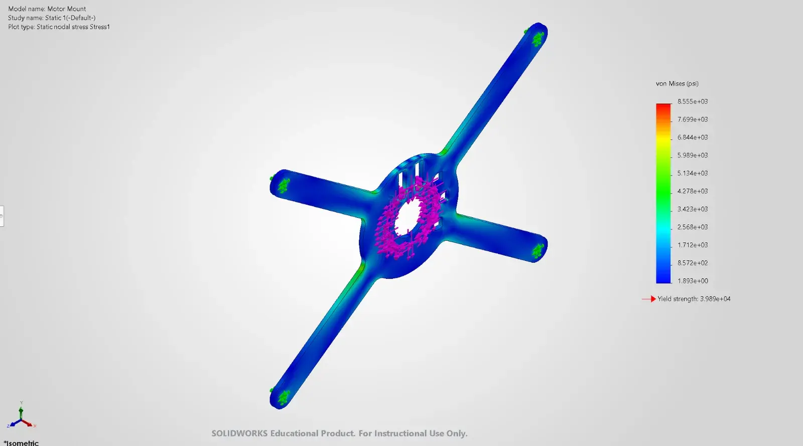
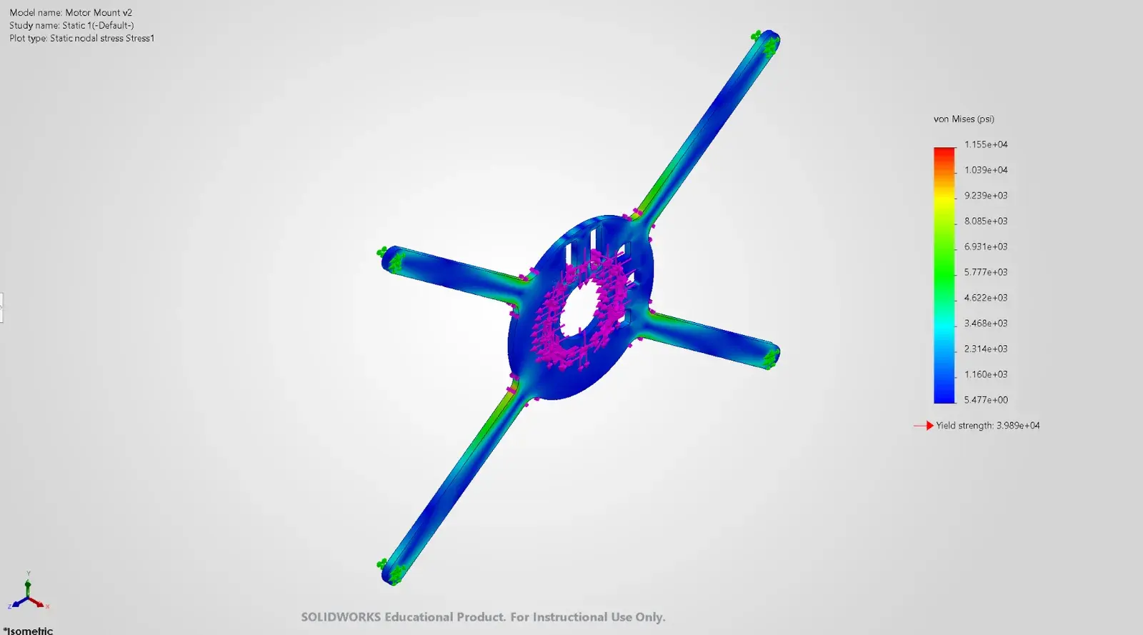
The stator-side mount is a single 6 mm plate of 6061-T6 aluminum, cut on the waterjet from the same 1/4 in stock as the Emrax mount: a hub around the 14-bolt circle with four straight arms to tabs on the corner tubes that run parallel to the shaft, each tab angled 35.84° to point at the motor center. The X shape keeps the load path from motor to frame short and direct, cutouts clear the coolant fittings and phase wires, and R0.5 in fillets relieve the arm roots.
The FEA fixed the four tab holes and loaded the bolt circle with the 1,604 N stator force, 303 N downward for a 3 g bump, and the 150 Nm peak torque, run in both directions because regenerative braking reverses it; the reversed case governed. A final run added 150 N along the shaft for cornering. Refining the mesh from 5 mm to 3 mm moved peak stress by under 1% (7,712 to 7,772 psi). The lowest factor of safety always sat at the edge of a tab hole, an artifact of the perfectly rigid fixture, so the margin was read at the arm roots instead.
V1 was overbuilt, with nearly the whole part far below yield, so the arms were narrowed from 32 mm to 20 mm. V2 is 24% lighter and still holds a factor of safety of about 6, or about 4.5 with cornering added. The cornering run moved the mount 1.2 mm along the shaft, which identified the axial direction as its weakest. The checks that remain before release are fatigue, since the torque reverses between acceleration and regeneration, bolt shear and bearing at the tab holes (each bolt sees under 1 kN), arm buckling, and tear-out at the tabs.
| Run | Arms | Mass | Arm-root stress | Factor of safety | Deflection |
|---|---|---|---|---|---|
| V1 | 32 mm | 1.34 lb | ~26 MPa | ~10 | 0.08 mm |
| V2 | 20 mm | 1.02 lb | 37 to 48 MPa | ~6 | 0.23 mm |
| V2 + cornering | 20 mm | 1.02 lb | ~62 MPa | ~4.5 | 1.2 mm axial |
Engine Mount Tab
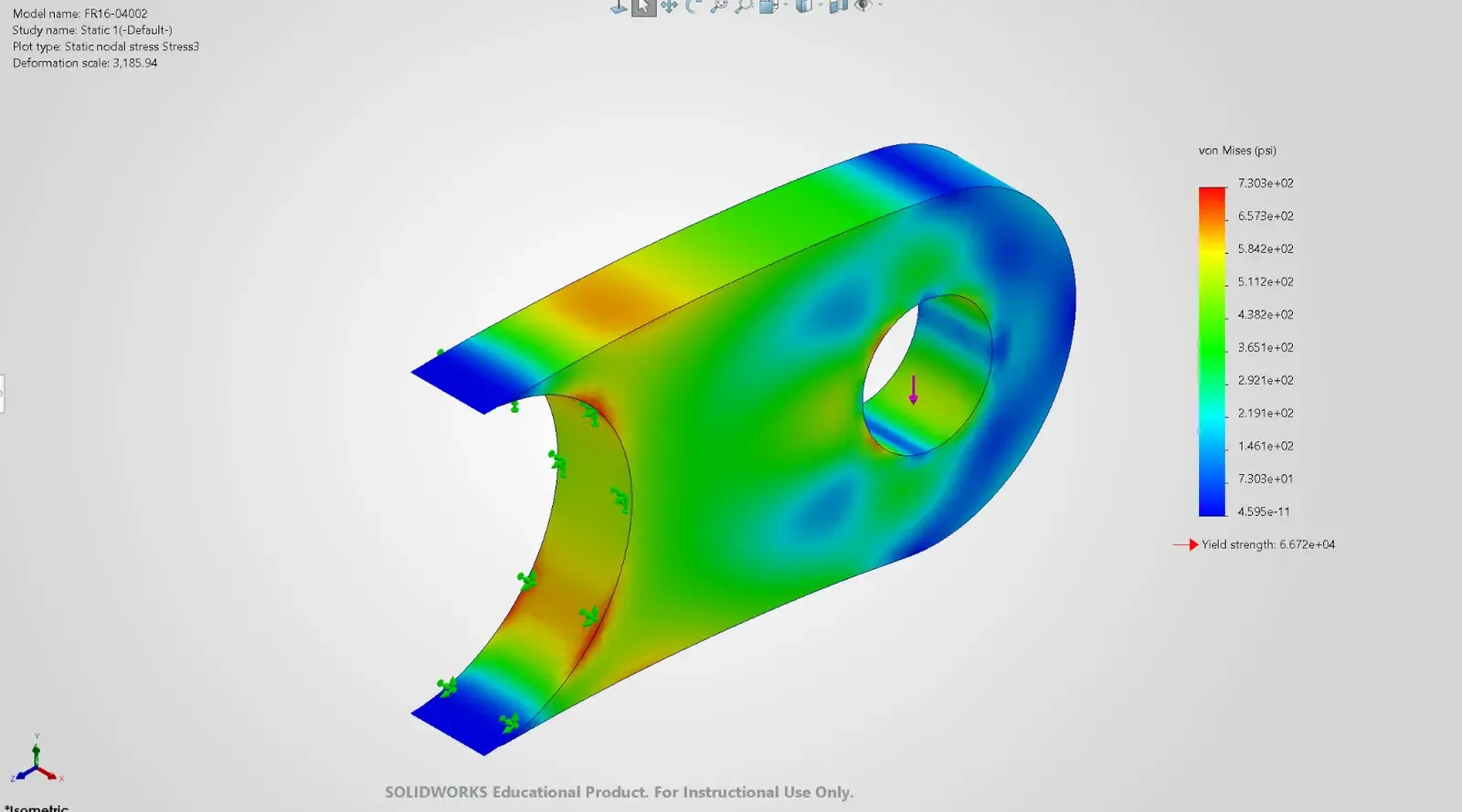
An engine mount tab (FR16-04002) was analyzed as a static study in normalized AISI 4130. The curved R0.50 end, which wraps a 1 in frame tube and is welded to it, was fixed. The load was a Yamaha YZF-R6 engine of about 120 lb shared evenly by four tabs, 30 lbf per tab, applied to the inside face of the bolt hole where the engine bolt bears and directed down in the plane of the tab, as if the engine hung from a tab projecting straight out of the frame.
Peak von Mises stress was 732 psi at the weld, where the bending moment is largest, against a 66,720 psi yield: a minimum factor of safety of about 91, with 0.000063 in of displacement. Refining the mesh moved the peak by about 1% (724.9 to 732.1 psi), so the result is mesh-independent. The static case leaves out bumps, braking, cornering, vibration, uneven load sharing between tabs, and any weakening of the steel at the weld, and the margin leaves substantial room for all of them.
Wheel Stand Weldment
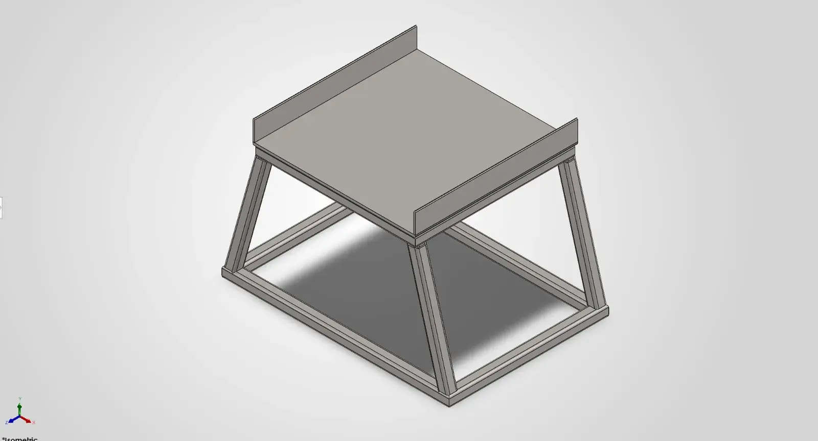
Four stands hold the car off the ground for suspension and underbody work. The layout follows JOES Racing’s 10 in stands, with a flat platform for the tire, roll stops so it cannot roll off, and a base wider than the top so it does not tip, but it is built as a square-tube steel weldment, closer to how the team fabricates, rather than in JOES’s 1/8 in aluminum.
A first layout sloped the legs diagonally into the corners, but the square tubes did not meet cleanly at the joints. Sloping the legs in one direction only made every joint a simple cut. The base, about 16.8 × 11.8 in, is widest in the direction the tire rolls, which is the way the car pushes against the roll stops; the 12 × 12 in top clears the 8 in tire, and the open sides let the stand slide under the tire from the side. The 10 in platform height gives room to reach the suspension without making the car hard to lift onto the stand or the stand easy to tip.
- Reference car: TR-26 at 546 lb, within the 430 to 605 lb range of other electric Formula SAE cars.
- Rear stand load at a 60% rear weight split: 546 × 0.6 / 2 ≈ 164 lb.
- Design load at a factor of safety of 2, since people work beneath the car: about 330 lb per stand.
The frame is AISI 1020 steel in 20 × 20 × 2 mm square tube, with a 3/16 in top plate that will not bend under the tire and 1/8 in flat bar roll stops. Mild steel is inexpensive, easy to weld, and comfortably strong for a few hundred pounds, and the finished stand weighs 16.8 lb, light enough for one person to carry.
Drawing Package
The front anti-roll bar assembly was modeled from the team’s drawings and released as a three-sheet package on the Triton Racing drawing template: an assembly sheet with a bill of materials and item balloons, and detail drawings of the torsion tube and the lever-arm boxes, each with its material, finish, and tolerance block.
The bar resists body roll by twisting only when the left and right suspension move by different amounts, so it adds roll stiffness without stiffening the ride over bumps that hit both wheels together. Its three adjustment holes set the lever arm on each box: the hole nearest the tube gives the shortest arm and the stiffest setting, and the farthest gives the softest. It matters most in skidpad, autocross, and endurance, and hardly at all in acceleration, where the car does not roll. The package also carries the drawings for the wheel stand and the engine mount tab.