Telecaster-Style Electric Guitar
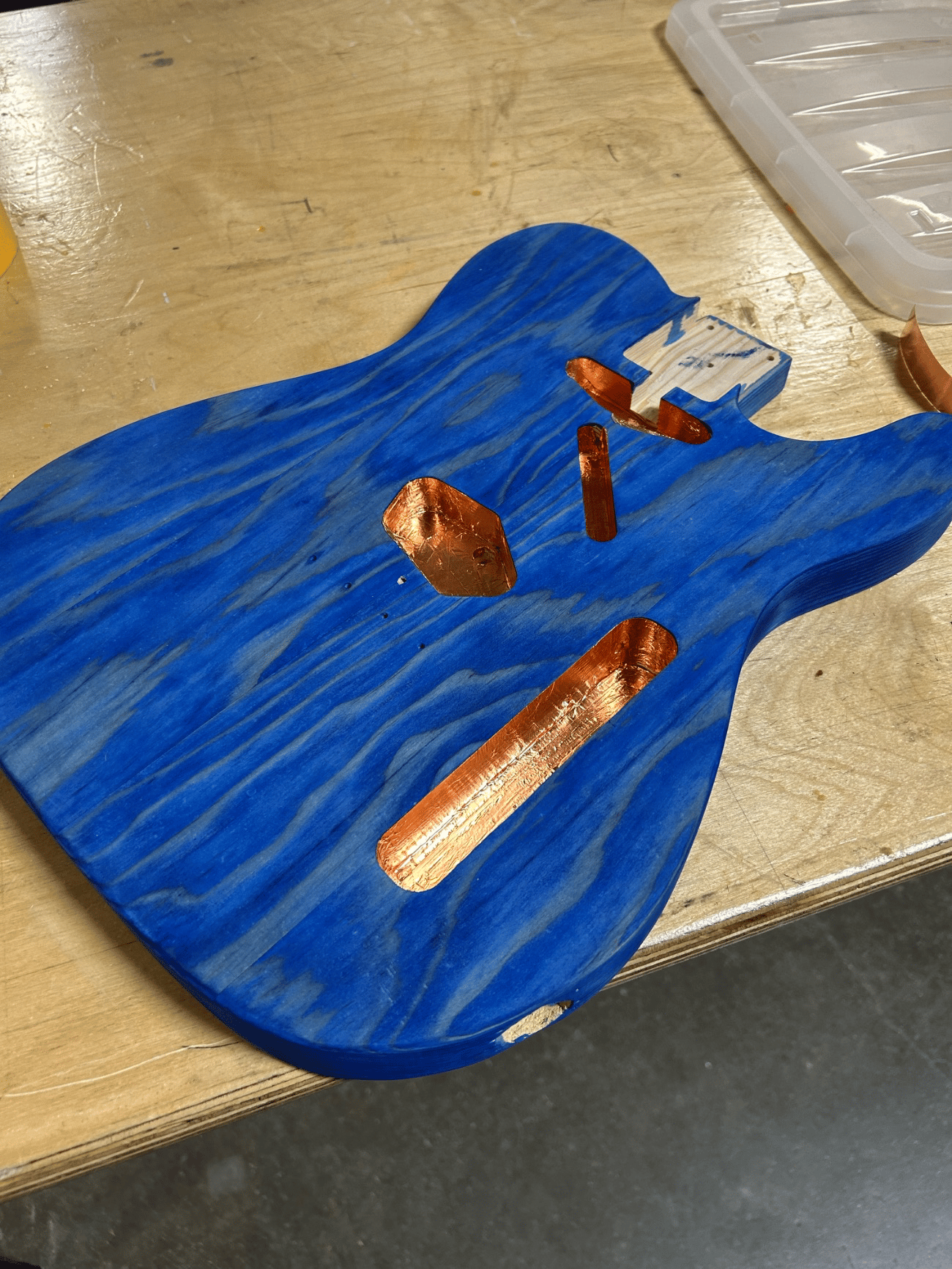
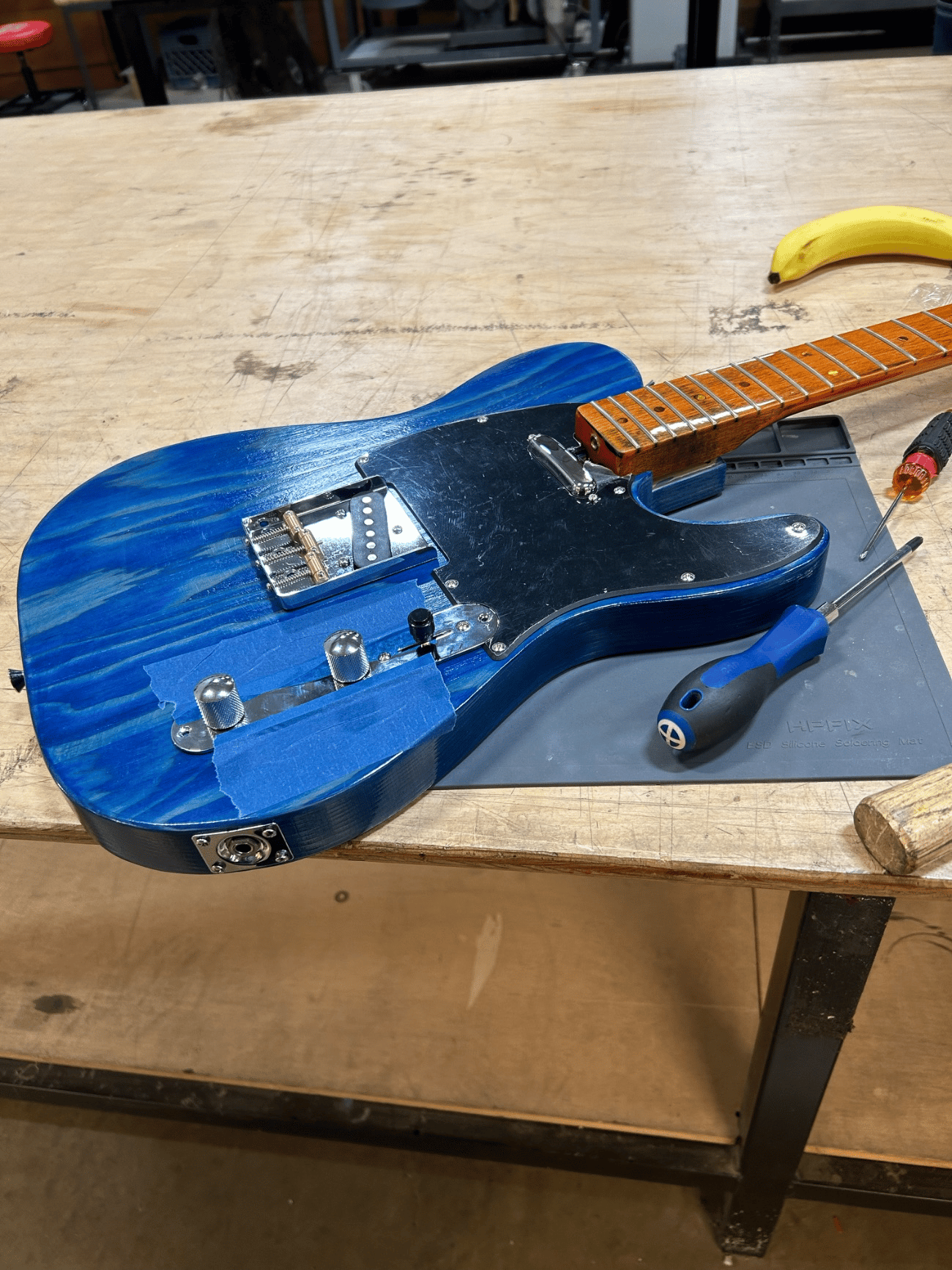
The geometry was dimensioned in SolidWorks against the instrument centerline and scale length, so the bridge position and neck angle resolved into one layout before any cutting. The slab was milled flat to a reference face and brought to thickness, the features routed to their modeled depths, and the body hand-dyed and sealed under ten coats of gloss. Final setup was a geometric adjustment, with the truss rod applying a counter-moment to hold neck relief against string tension.
Objective & Constraints
The objective was to build a solid-body electric guitar as a precision assembly, where playability depends on how accurately the bridge, pickup, and neck locate relative to one another rather than on craft alone.
A solid slab was chosen as the body so the structure would resist the pull of the strings without flexing out of tolerance, ruling out chambered or set-neck construction.
A translucent finish was specified from the start, which set the surface standard for the whole build: the wood had to be milled and sanded clean enough for color to read through it, since a dye reveals any flaw an opaque coat would hide.
CAD
The instrument was modeled in SolidWorks before any material was cut. Working from the instrument centerline and the scale length, the model fixed the body outline, the pickup and control cavities, and the neck pocket, setting where the bridge and neck would seat so the string path and pickup positions followed from a single layout.
Resolving that geometry up front meant the body could be cut to known dimensions instead of fitted by trial at the bench.
Fabrication
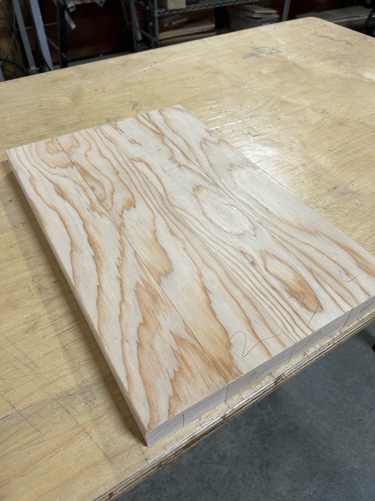
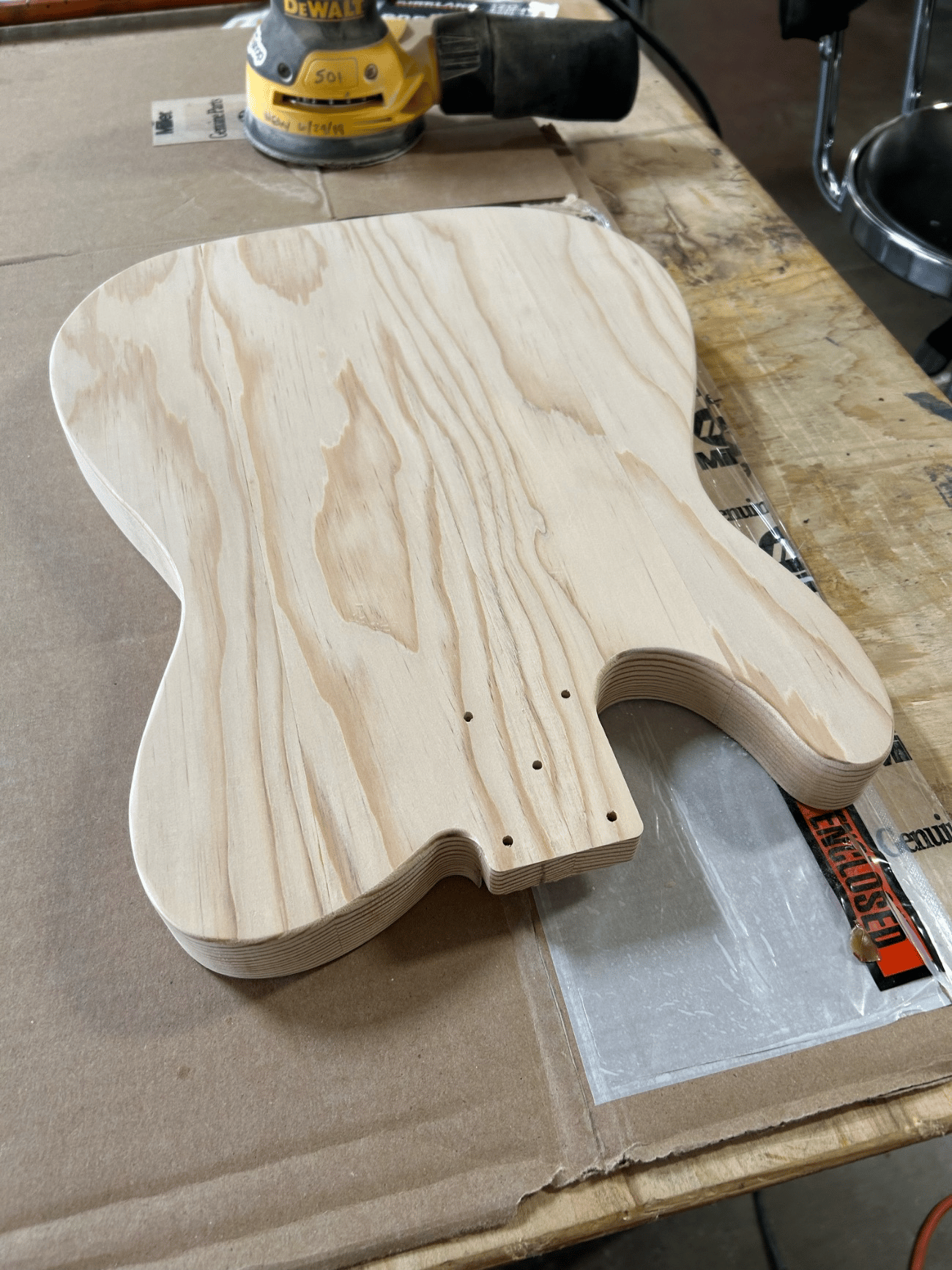
The glued slab was milled flat to establish a reference face, brought to final thickness, and the outline cut and faired to the line. The cavities and neck pocket were routed to the depths and positions from the model, wiring channels were drilled between them, and the edges were profiled with a router.
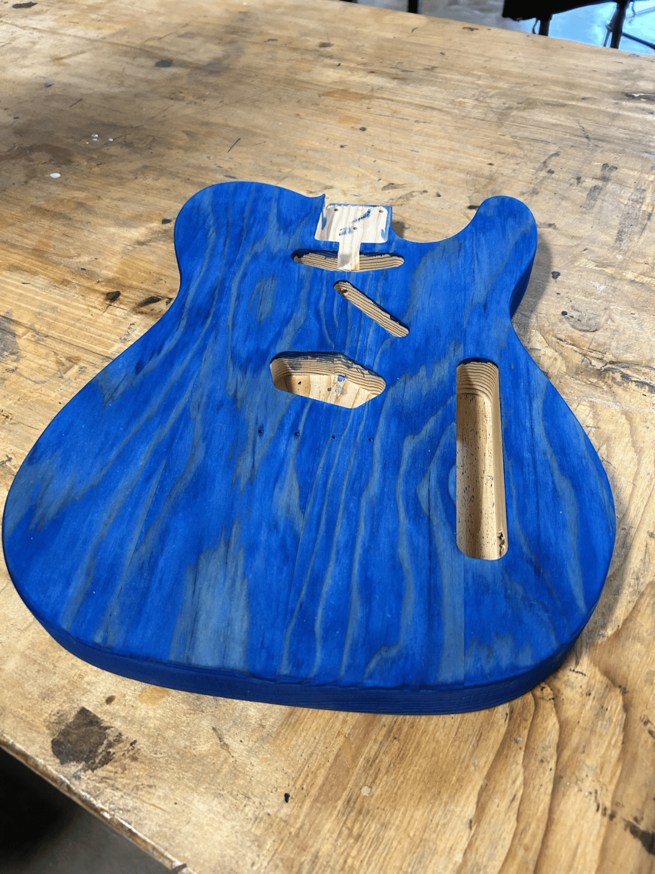
The body was then sanded through progressively finer grits, hand-dyed blue in successive coats so color built into the grain while the figure stayed visible, and sealed under ten coats of gloss worked to a level film.
Setup
With the hardware mounted into its cavities, the bridge, pickup, output jack, and volume control were soldered into a single signal path, and the neck was fitted and the strings drawn up to the tuners.
Strung to pitch, the neck carries the full string tension and is loaded in combined tension and bending, so it pulls into a forward bow. The truss rod runs through the neck as an adjustable counter element: tightening it applies an opposing bending moment that sets a small, even relief, fixing the clearance between the strings and the frets.
Final setup was therefore a matter of adjusting this geometry to specification.