FDM 3D Printer Build
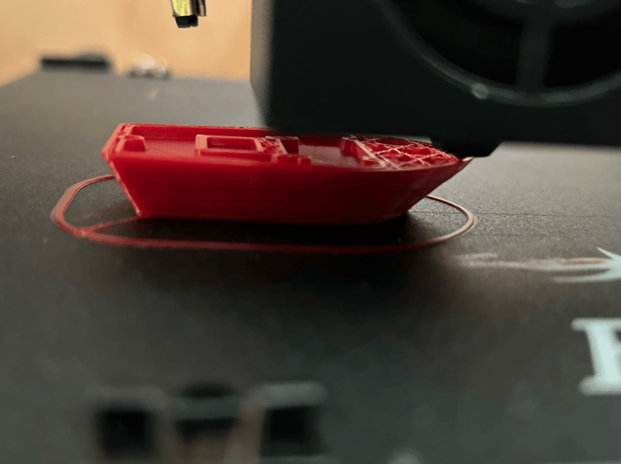
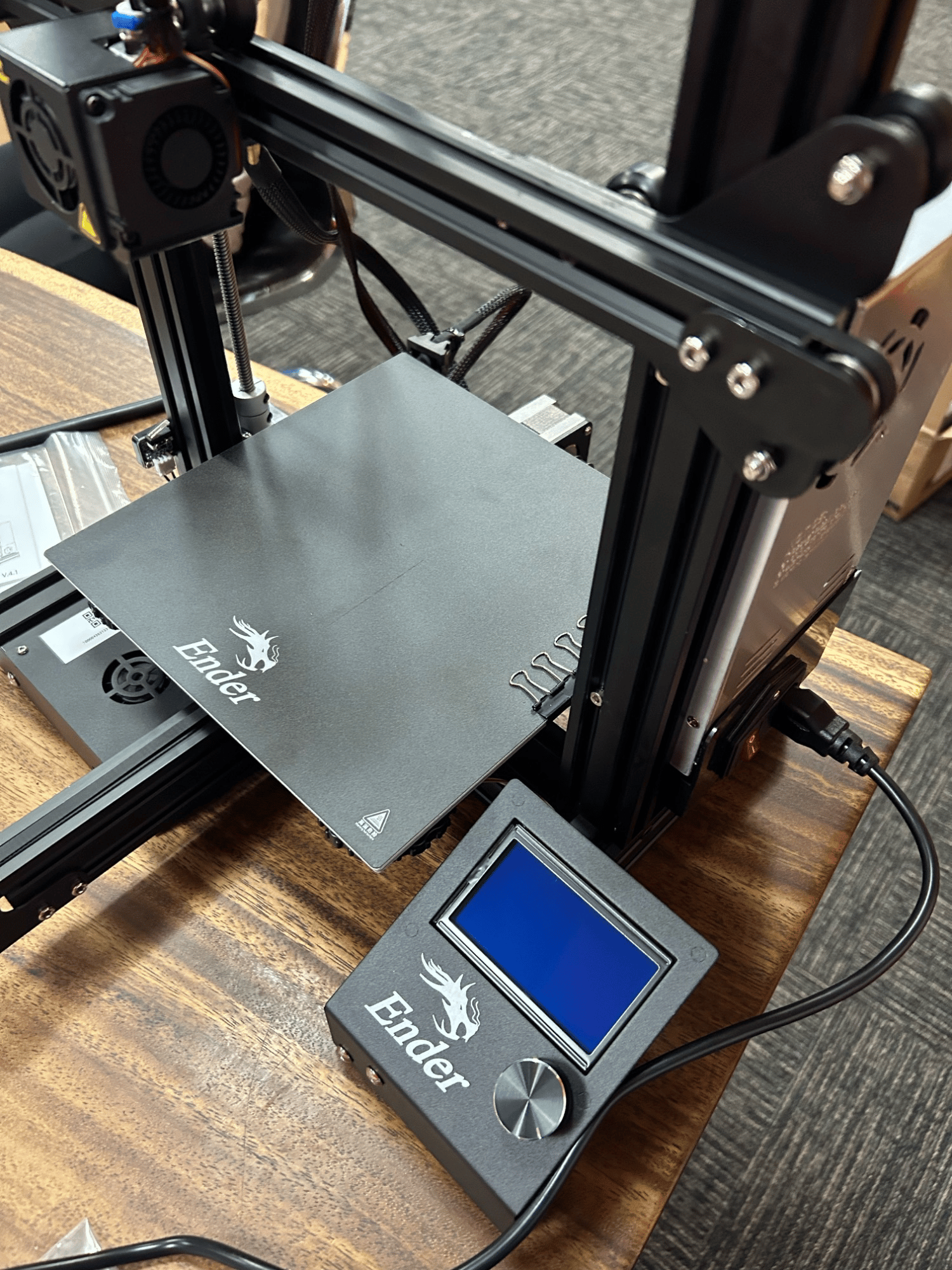
Assembled from its component parts, the platform is an aluminum-extrusion frame with a belt-driven gantry, a heated bed, and thermal runaway protection on the control board. Commissioning set first-layer adhesion through bed leveling and nozzle height, then verified extruder calibration so commanded extrusion matched delivered filament. A part was modeled, sliced, and printed on the finished machine across its 220 × 220 × 250 mm build volume, confirming the path from digital model to physical part.
Objective
The objective was to understand how an FDM printer works as an electromechanical system, and the most direct route was to build one from its component parts and bring it to the point where it prints reliably. A printer at this level reduces to aluminum extrusions, stepper motors, a gantry, an extruder, wiring, and a control board; assembling those by hand turns each connection and tolerance into something understood rather than assumed.
The working envelope is a 220 × 220 × 250 mm build volume on an aluminum-extrusion frame, with a heated bed and thermal runaway protection on the control board.
Assembly
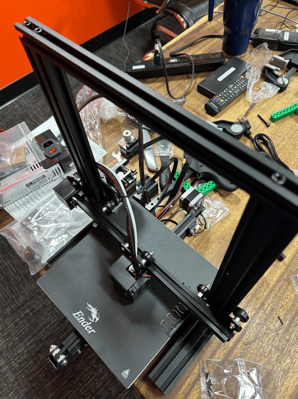
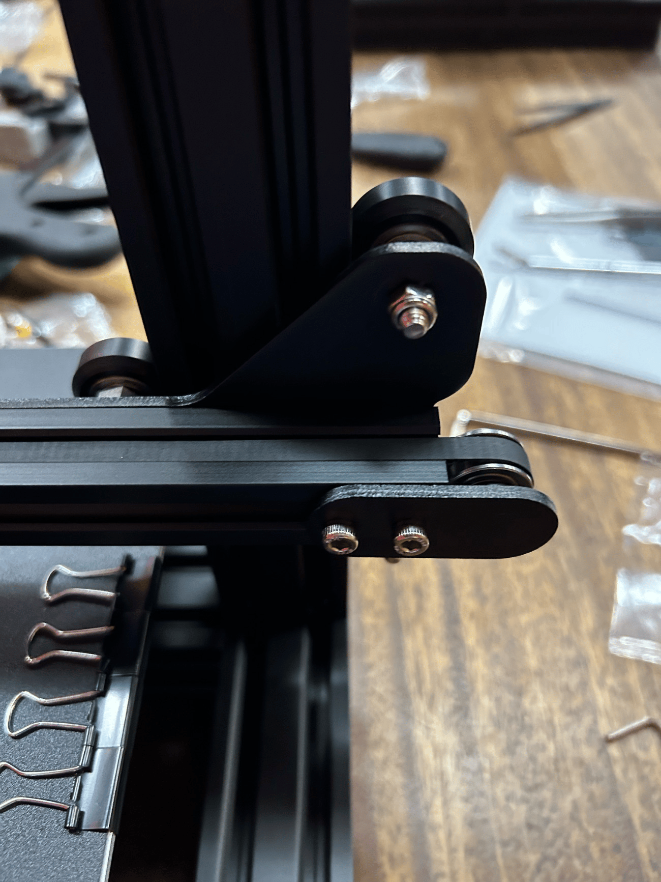
The frame went together from the base up. Vertical extrusions were bolted to the base, the X-axis extrusion mounted to the uprights, and the drive pulley fitted at the rear of the X axis. The gantry then slid onto the frame, and the spool tube and bracket were fastened in place.
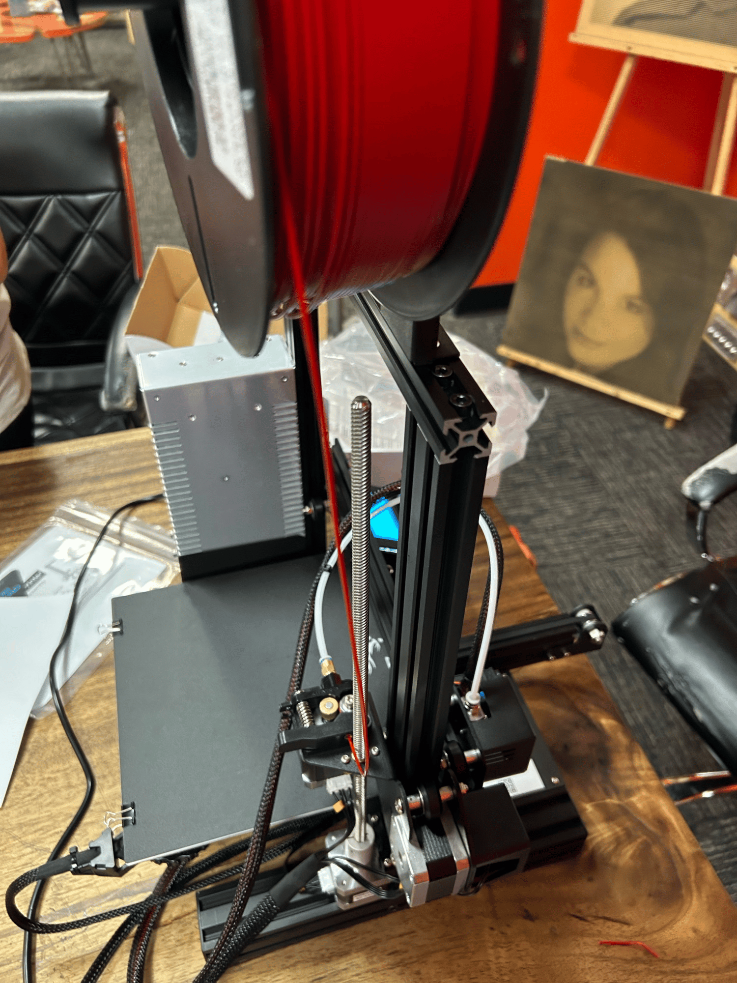
Wiring made the mechanics legible: connecting the extruder and X-axis motors and tracing the filament path from spool to hot end showed how the control board drives motion and feeds material. The geometry exposed here matters in use, since on a belt-and-V-roller system frame squareness and belt tension govern how faithfully the carriage follows commanded moves.
Commissioning
Assembly alone does not produce good prints; the machine has to be commissioned. Leveling the bed and setting nozzle height established a flat, well-adhered first layer, the datum every later layer references. Verifying extruder calibration so commanded extrusion matched delivered filament addressed the other half of print quality, since over- or under-extrusion shows up in both surface finish and dimensions.
Validation
The final step turned the machine to its purpose. A part modeled in CAD and run through a slicer printed on the finished printer, closing the loop from digital model to physical part and confirming the assembled, commissioned machine behaved as intended.